


Hospital Retrofitting
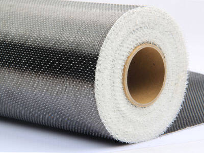
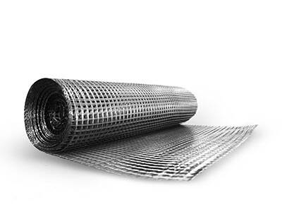
Carbon Fiber Reinforced Polymer
Because of the requirements of the architectural design of the ward building, it is necessary to add new public toilets, elevators, etc. It is precisely because of the above-mentioned functional changes that the load changes, and local beams will not meet the requirements of the current reconstruction design. , Need to be reinforced with carbon fiber reinforced polymer(CFRP)

Reinforcement project overview
The teaching experiment building of the University of Chinese Medicine was completed in 2003. Reinforced concrete frame shear wall structure, one basement level, 15 floors above ground. Most of the original design was for offices and classrooms (live load was 2.0KN/㎡. Later, the building was handed over to the Provincial Hospital of Traditional Chinese Medicine, which decided to transform this building into a ward building. The current ward buildings are all designed as hotel standard rooms. It is necessary to add toilets and part of the partition wall. Because of the requirements of the architectural design of the ward building, it is necessary to add new public toilets, elevators, etc. It is precisely because of the above-mentioned functional changes that the load changes, and local beams will not meet the requirements of the current reconstruction design. , Need to be reinforced.
After multiple program demonstrations and economic and technical feasibility comparisons, and the construction period requirements are particularly urgent, it is decided to use carbon fiber composite materials for reinforcement.

Reinforced design
Basic assumption
The calculation of ultimate bearing capacity of concrete beams strengthened with carbon fiber materials adopts the following basic assumptions:
(1) The effect of concrete in the tension zone is ignored;
(2) After the beam is flexed, the strain of concrete, steel and carbon fiber conforms to the assumption of flat section;
(3) Carbon fiber material adopts linear elastic stress-strain relationship: ocf=Ecf*ecf and ecf<0.01.
In this design, 2 layers of 300mm wide carbon fiber cloth are pasted on the bottom of the beam. After reinforcement, the design value of the maximum bending moment of this beam has been increased by 22%.
Construction method
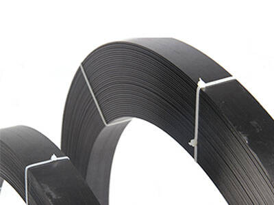
In order to strengthen the tracing of the carbon fiber cloth at the bottom of the beam and increase the shear resistance of the beam, two 200mm wide U-shaped pushes are pasted on each side of the beam end, and two 100mm wide U-shaped boxes are pasted on each side of the intersection of the primary and secondary beams.
The sticking height of U-shaped sticking should be taken as the height of the component section. For the U-shaped paste form, it is advisable to paste the longitudinal carbon fiber sheet bead on the upper end.
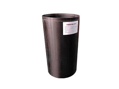
Taking into account the factors that are greatly affected by the construction site when the carbon fiber cloth is pasted in multiple layers, it is recommended that the number of layers of carbon fiber cloth pasted on the bending member should not exceed 3 layers.


