


Carbon Fiber Sheet Strengthening
Application of Carbon Fiber Sheet Reinforcement Technology in Reinforced Concrete Structure Repair of Power Station
The cracks in the roof beams of the GIS building and the corbels of the underground powerhouse have been grouted and reinforced with carbon fiber. The bending, tensile and shear strength of the concrete components have been effectively improved.
Project Overview
Ertan Hydropower Station is located on the main stream of the Yalong River in Panzhihua City, Sichuan Province. It is a large-scale water conservancy hub with a total installed capacity of 3300MW. The power station hub buildings are composed of barrages, flood discharge buildings, energy dissipation buildings, underground powerhouses, water diversion and tailwater buildings, and 500kV fully enclosed gas-insulated combined switch stations (GIS buildings).
The GIS building is the 500kV switchyard of Ertan Hydropower Station, the main structure size is 131.4x18.6x22.2m (length X width x height), is a cast-in-place reinforced concrete frame structure, and the foundation is located on a relatively complete rock foundation. The roof beam spans the entire building, without column support in the middle, and 500kV outlet lines are arranged on the roof.
The underground powerhouse system takes the main powerhouse and installation room, main transformer room, and tail water surge tank as the main body. Including bus tunnels, access tunnels, drainage tunnels, exhaust tunnels, cable inclined shafts, upper dam elevator shafts and other caverns. A group of underground caverns that overlap and crisscross each other are formed. The main building is 280.3m long and has a span of 25.5m. The generator layer and the turbine layer of the main powerhouse are cast-in-place reinforced concrete frame slab beam structures. The beams are supported by square wind shields and independent columns. The beams are arranged neatly, and the units are separated by expansion joints.
2 Existing problems
During the pre-flood inspection in March 2003, it was found that most of the roof beams of the 500kV fully enclosed gas insulated switchgear station (GIS building) had cracks. Especially the roof girder of the 29th axis has cracks and large bending deformation, causing the bottom of the girder and the bridge crane guardrail to scrape. Most of the corbels and the ends of the simply supported beams on the corbels in the generator layer and turbine layer of the underground powerhouse have cracks. As soon as the problem was discovered, it attracted great attention. Immediately organize relevant professionals from the original design institute to conduct on-site investigations, verify the original design materials and drawings, calculate structural loads, cross-section reinforcements, beam deflection values, etc., and conduct peeling inspections on part of the cracked plaster layer.
It was found that there were 10 symmetrical cracks on both sides of the abdomen of the 29th axis of the GIS building with a width of about 0.3 to 0.6 mm. The cracks started from the bottom of the slab and extended downwards and disappeared at a distance of 100-200mm from the beam, without penetrating through the bottom of the beam. No through cracks exceeding 0.2 mm were found at the bottom of the beam. After cutting off the plaster layer on the surface of the beam, it was found that the cracks on both sides of the beam abdomen reached the concrete layer of the beam body. It was preliminarily judged that the symmetrical cracks on both sides of the beam may have penetrated the beam body. The inspection also found that most of the other beams have cracks, the protective layer is extremely thin, some stirrups are exposed, and the sides of the beam waist web are recessed to the inside. The cracks in the abdomen of the beam may be due to insufficient concrete protection layer and improper maintenance or improper concrete mix ratio during construction.
There are oblique cracks to varying degrees on the outer side of the top edge of the corbel on the generator layer and the turbine layer of the underground powerhouse and the lower edge of the simply supported beam on the corbel. Some serious cracks have penetrated from the upper simply supported beam to the lower corbel. After stripping the plaster layer on the side surface (about 2cm deep) where the simply supported beam and the corbel were combined, it was found that most of the corbels with cracks were not embedded with a steel backing plate, which was inconsistent with the original design. No cracks or very small cracks were found in any corbels with steel backing plates embedded. The cause of the cracks is most likely due to the fact that steel plates are not embedded on the surface of the corbel and the corresponding beam bottom. When the temperature changes and the concrete shrinks and the plant is operating vibration, the friction between the beam bottom and the corbel is relatively large, causing the beam end and the corbel to crack .
3 Structural carbon fiber reinforcement treatment
3.1 Principles and advantages of carbon fiber reinforcement
3.1.1 Principle
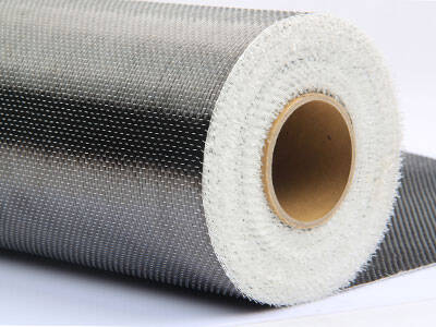
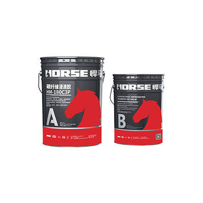
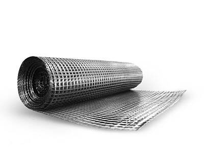
Carbon fiber cloth reinforcement structure technology is a new type of structure reinforcement technology. There are mainly two types of carbon fiber materials used in the reinforcement and repair of concrete structures: carbon fiber materials and supporting resins. Among them, the tensile strength of carbon fiber is ten times that of construction steel, and the modulus of elasticity is equivalent to that of steel, and its construction performance and durability are good. It is a good reinforcement and repair material. The matching resin includes bottom resin, leveling resin and bonding resin. The function of the first two is to improve the bonding quality of carbon fiber. The role of the latter is to enable carbon fiber and concrete to form a composite whole and work together to improve the flexural and shear bearing capacity of structural members to achieve the purpose of strengthening and strengthening structural members.
3.1.2 Advantages Compared with traditional reinforcement technology, carbon fiber cloth reinforcement technology has obvious advantages:
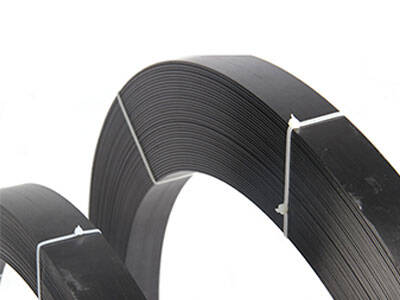
(1) High strength: Carbon fiber cloth has excellent physical and mechanical properties, its tensile strength is 8 times that of ordinary steel, reaching more than 4000MPa, and its elastic modulus is close to steel, which is suitable for reinforcement and repair of reinforced concrete.
(2) Stable performance: Carbon fiber cloth has good durability and chemical corrosion resistance, is resistant to acid, alkali, salt and atmospheric corrosion, and does not require regular maintenance. It protects the internal concrete structure and can achieve the purpose of double reinforcement and repair. .
(3) Light weight: The commonly used specifications of carbon fiber cloth are 200g/m and 300g/m, and the thickness is 0.111mm and 0.167mm respectively. The white weight is light, and the structural weight and cross-sectional size are basically not increased.
(4) Convenient construction: No wet work, no large construction equipment, no on-site fixing facilities, carbon fiber cloth can be cut arbitrarily, simple construction, no dust and noise pollution, and short construction period.
(5) The construction quality is easy to guarantee: the carbon fiber cloth is soft, even if the surface to be reinforced is not very smooth, the adhesive material glue can be used to ensure effective adhesion of 100% of the area.
3.2 Reinforcing materials
It is selected to try not to affect the normal operation of the power plant, not to damage the original reinforcement of the structure, restore the original appearance of the structure, and overcome the shrinkage of the concrete. Increase the bending and shear resistance of the structure to prevent new cracks, and use carbon fiber sheets to strengthen the roof beams and corbel cracks. The carbon fiber cloth adopts HM-30 type carbon fiber cloth, with a dead weight of 300 and a thickness of 0.167mm; the binding material adopts the matching HM type carbon fiber resin.
3.3 Reinforcement of roof beams of GIS building
3.3.1 Crack repair
According to the width and depth of the cracks in the roof beam of the GIS building, the surface is chiseled with a "U" groove method, and the surface is smeared and sealed with a fast sealing material, and when necessary, HM-120L structural jointing glue is used for chemical grouting. Sewing treatment.
3.3.2 Structural reinforcement
On both sides of the 29th axis roof beam, 400mm away from the bottom of the beam and the surface of the beam, a layer of carbon fiber with a width of 300mm is pasted along the length of the beam to overcome the stress caused by the shrinkage of the concrete. After overcoming the concrete shrinkage, in order to compensate for the loss of the beam's bearing capacity after cracking and deformation, the beam's flexural and shear resistance capabilities should also be enhanced. A layer of carbon fiber with a width of 500mm is pasted along the whole length of the bottom of the beam to improve the bending resistance of the beam. Paste a layer of "U"-shaped carbon fiber hoops with a width of 300mm along the length of the beam with a spacing of 200mm to improve the shear resistance of the beam, as shown in Figure 1. For other roof beams with cracks, since cracks mostly appear at the ends of the beams, a layer of 150mm wide "U"-shaped carbon fiber hoops are pasted on the ends of the beams with a spacing of 200mm and a length of not less than 2m to improve the beam's shear resistance. ability. At the same time, in order to prevent cracks on the side of the beam, a layer of carbon fiber with a width of 150mm is pasted on both sides of the beam, 400mm from the bottom of the beam and the beam surface along the length of the beam to overcome the stress caused by the shrinkage of the concrete, as shown in Figure 2. .

3.4 Reinforcement of corbels and beams in underground powerhouse
3.4.1 Crack repair
In order to restore the integrity of the structure as much as possible, prevent the seam surface from continuing to develop, and take into account that the bonding strength of the seam-grouting material should not be too high. Therefore, ultra-fine cement-based infusion material-type inorganic bonding infusion material is used to fill the joints, and then the surface of the cracks is smeared and sealed with a fast sealing material.
3.4.2 Structural reinforcement
The reinforcement of the corbels and beams of the underground powerhouse, after design and calculation, the reinforcement of each structure is as follows:
(1) The corbel adopts three-layer ring stitching hoop: the height of the first and second layers is 0.5m, and the height of the third layer is 0.2m;
(2) The end of the beam support is pasted in two layers along the length of the beam, with a height of 0.5m and a length of 1.5m;
(3) The square corbel adopts a "U"-shaped hoop and is pasted with three layers, which is 0.44m high and 1.5m long. As shown in Figures 3 and 4.


4 Conclusion
The cracks in the roof beams of the GIS building and the corbels of the underground powerhouse have been grouted and reinforced with carbon fiber. The bending, tensile and shear strength of the concrete components have been effectively improved. Then the stress caused by the shrinkage of the concrete is overcome and new cracks can be prevented. The carbon fiber cloth reinforcement project is convenient for construction, and the time is short, and the appearance of the original structure can be basically guaranteed after the repair. After the project was completed and put into operation, the main structure has not seen any abnormalities so far, and a good reinforcement effect has been achieved.


