


Solutions
Horse Construction offers full range of structural strengthening materials with technical supports, documentation supports, products supports, project supports.
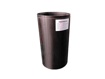
FRP Pile Jackets
The underwater FRP (Fiber-Reinforced Polymer) jacket method is a mainstream technique for reinforcing underwater structures—such as bridge piles, wharf piers, and sluice gate columns—without the need for cofferdams.
The core principle involves wrapping a damaged pile with a factory-prefabricated fiberglass jacket and injecting underwater epoxy grout to create a composite protective layer consisting of the jacket and the cured grout; this simultaneously achieves structural reinforcement and long-term corrosion protection. This method is suitable for repairing defects such as concrete erosion, exposed reinforcement, carbonation, and cracking, offering significant construction advantages—particularly in environments characterized by deep water, low visibility, and strong tides.
However, on-site reviews of numerous underwater bridge reinforcement projects reveal that over 95% of common grouting issues—such as grout leakage at the base, joints, sidewalls, or overflow at the top—are not caused by material defects. Instead, they stem from a lack of detailed control across six critical areas: sealing system failure, inadequate substrate preparation, sleeve installation errors, loss of control over the grouting process, improper material selection, and disturbances from the underwater environment. These leakage issues range from excessive material waste and incomplete filling to severe consequences such as voids between the sleeve and pile foundation and a significant reduction in load-bearing capacity; in worst-case scenarios, they necessitate remedial work—including clearing the sleeve and re-deploying divers—thereby drastically increasing project timelines and costs.
Primary Culprit 1: Failure of the bottom elastic sealing system
(Accounts for approximately 80% of all cases of large-scale grout leakage; it is the core and most common root cause.)
At the onset of grouting, a continuous, heavy surge of grout—accompanied by turbid water—erupted from the bottom of the sleeve. Consequently, the base seal failed to form a closed chamber; the grout was rapidly washed away by the flowing water, preventing the buildup of effective hydrostatic pressure within the sleeve and resulting in an incompletely filled cavity.
Specific Contributing Factors
Detailed Breakdown of Causes
(1) Improper selection and dimensional deviation of the sealing strip: According to the T/SDHTS 00017—2025 standard, the bottom circumferential seal should be a water-swelling rubber strip. Its diameter should be 1.5 to 2.0 times the designed grouting layer thickness, and it must possess a compression recovery rate of at least 40%. Common on-site violations include:
Substitution with ordinary closed-cell foam strips, which lack sufficient compression and recovery capabilities, failing to fill gaps effectively when the pile exhibits significant ovality;
Using a sealing strip with an undersized diameter, resulting in continuous gaps between the strip and the pile surface;
Incorrect use of ordinary solid rubber strips that lack water-swelling properties, leading to permanent deformation after prolonged underwater compression.
(2) Non-compliant installation and splicing of the sealing strip: Splicing overlap length is less than 100 mm, or the ends merely abut without welding or bonding, allowing water to seep through the joint;
The sealing strip is not fully seated in the groove at the lower inner edge of the sleeve, leaving sections suspended;
During underwater installation, the strip is propped up by silt or marine growth at the pile base, creating water leakage channels;
Failure to clean the pile surface prior to installation, causing sharp protrusions (such as seashells or rebar ends) to puncture the sealing strip.
(3) Lack of pre-treatment for defects at the pile base: Underwater sections of piles often suffer from deep pits, honeycombing, or localized notches due to long-term scouring. When the sleeve is installed directly over these areas, the sealing strip—limited by its compression range—cannot conform to the uneven surface, creating permanent channels for grout leakage. Such issues are often concealed, and leakage is frequently misattributed to "sealing strip quality defects."
(4) Positioning errors during sleeve lowering, causing compression damage to the sealing strip: Failure to strictly align the sleeve with the pile's centerline during hoisting causes the sealing strip to tear due to excessive compression on one side while losing contact entirely on the other. This issue is particularly pronounced when the pile exhibits significant ovality (with axis deviation exceeding 20 mm).
Culprit No. 2: Imperfect Sealing of the Fiberglass Sleeve Locking Joint
(The second most significant source of continuous grout leakage from the sidewall—after the bottom seal—this typically manifests as fine-line leakage that is difficult to detect early, posing risks with delayed consequences.)
When fiberglass sleeves are assembled on-site using interlocking male and female connectors, inadequate sealing of the locking grooves allows grouting pressure to force the grout outward through the seams. As the leakage volume is typically small—manifesting as thin, thread-like lines—it often goes unnoticed in murky water conditions; consequently, traces of hardened grout on the sleeve's exterior are frequently discovered only after the grouting process is complete, by which time the internal filling is no longer dense or fully consolidated.
Key Contributing Factors
(1) Insufficient adhesive application in the locking groove: To meet tight schedules, workers applied adhesive only to sections of the groove or created a layer thinner than 1 mm, resulting in continuous gaps after interlocking. The underwater grouting pressure (0.05–0.15 MPa) was sufficient to force the grout out through these gaps.
(2) Sleeve misalignment and incomplete locking engagement: When the pile foundation was elliptical, eccentric, or irregular in diameter, the sleeve had to be forcibly pulled shut; this caused axial misalignment (exceeding 5 mm) between the male and female locking components, creating a narrow, water-permeable gap along the interlocking interface.
(3) Excessive spacing of fastening straps or failure to tighten in stages: Although specifications require self-tapping screw spacing of 80–120 mm, on-site spacing often exceeded 200 mm, leading to uneven stress distribution. Failure to tighten the fastening straps symmetrically from the center outward caused the sleeve ends to flare open like a trumpet; furthermore, the lack of re-tightening before grouting allowed the sleeve to expand under internal pressure.
(4) Lack of water-sealing measures at the vertical joints of segmented sleeves: Projects requiring increased height involved splicing multiple sleeve segments, yet no annular water-sealing gaskets were installed at the mating end faces; this resulted in continuous leakage through the inter-segment gaps, which proved extremely difficult to repair underwater.
Culprit No. 3: Inadequate pre-treatment of the pile base surface, leaving hidden pathways for grout leakage
(This step is most easily overlooked, and the leakage is particularly insidious; grout migrates through internal defects in the pile, often leading to the mistaken conclusion that the issue lies with the sleeve seal.)
Underwater piles are subject to prolonged water scour, biofouling, and chemical erosion, resulting in a generally poor surface condition. If the surface is not properly treated before the sleeve is installed, the pressurized grout infiltrates internal voids, cracks, and cavities within the concrete. It spreads along these pre-existing defects and eventually seeps out through tiny gaps at the sleeve's edge, creating the appearance of a "sleeve joint leak," even though the actual source of the leakage is within the pile body itself.
Key Contributing Factors
Only high-pressure water washing was performed; loose concrete, carbonated layers, and rust-swollen protective layers were not chipped away, resulting in substandard bond strength at the interface;
Cracks with widths ≥ 0.2 mm were not sealed by injecting adhesive along the crack line, causing grout leakage during the grouting process;
Pits caused by rebar corrosion and grooves caused by erosion were not filled and leveled in layers; the gap between the sleeve and the pile foundation varied drastically in width, causing grout to be obstructed in narrow sections while flowing rapidly through others;
Surface contaminants such as seaweed and barnacles were not thoroughly removed, impairing the bond between the epoxy grout and the substrate.
Primary Cause No. 4: Loss of control over grouting process parameters, causing pressure to breach the sealing system
(Hydrostatic pressure resulting from excessive process parameters can directly rupture the sealing system; the failure is sudden and the consequences severe.)
Three major process-related triggers:
(1) Excessive single-lift grouting height leading to hydrostatic pressure exceeding limits. The formula for calculating the hydrostatic pressure of the grout column inside the sleeve is P = ρ × g × h (where ρ ≈ 1,800 kg/m³, the density of underwater epoxy grout). At a grouting height of 2 m, the pressure at the base is approximately 0.035 MPa; at 4 m, it approaches 0.07 MPa—levels that near or even exceed the pressure-bearing limits of most sealing systems.
Standards require the grouting height for a single lift to be controlled between 1.5 and 2.0 m, with subsequent grouting occurring only after the lower layer of grout has undergone initial set (usually ≥ 6 hours). On-site, however, the entire sleeve is often grouted in a single operation in violation of these rules, causing the bottom sealing strip to be squeezed out or torn under sustained high pressure.
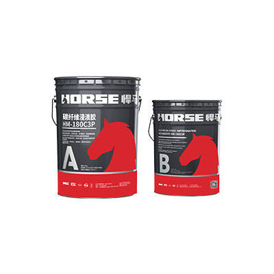
(2) Loss of control over the grout mix ratio and excessive fluidity. Failure to strictly follow the manufacturer's A:B mixing ratio or the arbitrary addition of water for dilution leads to reduced grout viscosity and increased bleeding rates;
When the bleeding rate is too high, the aqueous phase preferentially seeps through micro-gaps, creating channels for continuous grout leakage;
Insufficient mixing time (should be ≥ 3 min) results in incomplete component reaction, leading to inadequate bond strength after curing and subsequent shrinkage cracking.
(3) Improper grouting speed and method causing air pressure surges. During rapid grouting from one side, air trapped inside the sleeve cannot escape promptly through the top vent, creating air-lock pressure (ranging from 0.02 to 0.05 MPa); this pressure combines with the hydrostatic pressure to exert a combined impact on the joint seal.
Insights into Underwater Grouting Leakage in FRP Pile Jackets(2)
You can find anything here you are in need of, have a trust trying on these products, you will find the big difference after that.

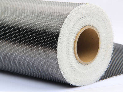
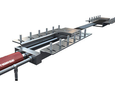
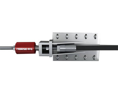
A heavy-duty carbon/glass fiber reinforced polymer(FRP) jacket pile protection system with epoxy grout
